


Understanding the phase diagram of iron-carbon alloys
In the vast field of materials science, iron-carbon alloys undoubtedly occupy an important position. From steel products in daily life to precision components in high-end technology fields, iron-carbon alloys are everywhere. The iron-carbon metallographic structure diagram, as the key to reveal the secrets of the internal microstructure of these alloys, has immeasurable value for understanding the properties of the alloy and optimizing the composition and process of the alloy. This article will provide a detailed interpretation of a typical iron-carbon metallographic structure diagram, in order to unveil the mystery of this microscopic world for readers.
- Overview of iron-carbon metallographic structure diagram
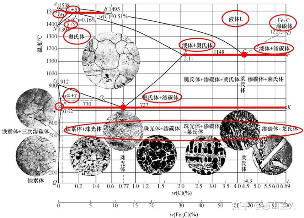
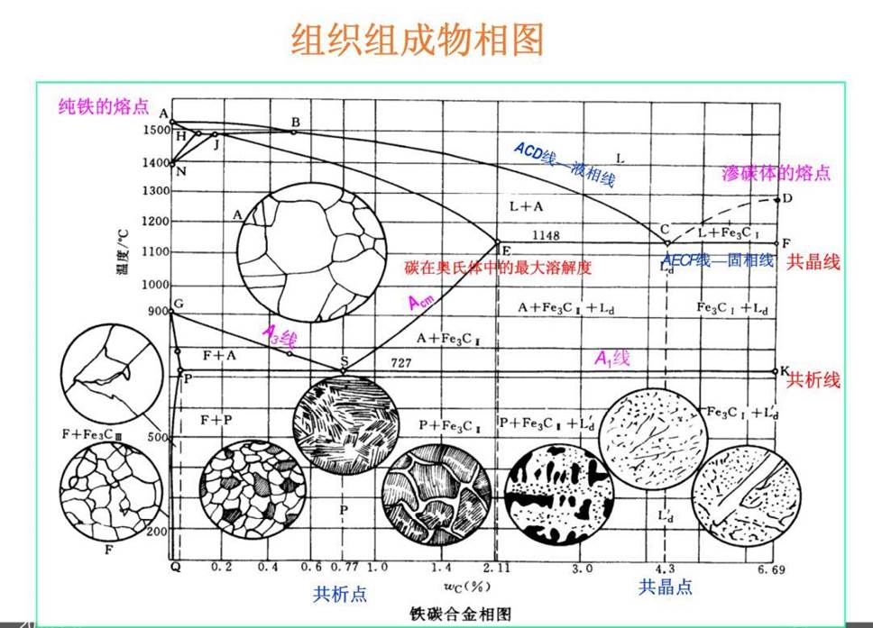
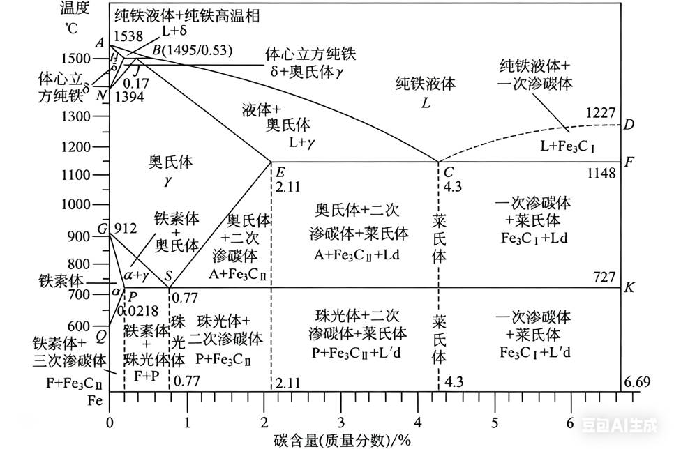
The iron-carbon metallographic structure diagram, as the name suggests, is a graph describing the internal structure and phase transition process of the iron-carbon alloy under different temperatures and carbon contents. This chart usually combines phase diagrams and metallographic photos, and through intuitive images and precise data, it shows the formation, evolution and relationship between each phase state during the process of cooling from liquid state to room temperature.
- Detailed interpretation of iron-carbon metallographic structure diagram
- The initial state of pure iron and iron-carbon alloys
On the left side of the iron-carbon metallographic structure diagram, we usually see the melting point line of pure iron, that is, the melting point of iron at standard atmospheric pressure is 1538°C. When pure iron is heated to this temperature, it will change from solid to liquid to form pure iron liquid. However, in practical applications, we are more exposed to iron-carbon alloys, that is, mixtures of iron and carbon. The melting point of these alloys gradually decreases with the increase in carbon content, but remains generally within a higher temperature range.
-
- Formation and evolution of high temperature phases
As the temperature drops, the liquid metal in the iron-carbon alloy begins to undergo a phase change. In high-temperature areas close to the melting point, the δ phase (also known as high-temperature ferrite) will first form in the alloy. This phase state is more common in pure iron, but in alloys containing a certain amount of carbon, its stability will be affected by carbon atoms. As the temperature further decreases, the delta phase will gradually transform into a face-centered cubic austenite (y phase). Austenitic is the stable phase of iron carbon alloy at high temperatures, with good plasticity and toughness, and is the basis of many heat treatment processes.
-
- The emergence and impact of cementite
In ferrocarbon alloys, the presence of carbon elements has a decisive impact on the structure and performance of the alloy. When the carbon content in the alloy exceeds a certain limit, cementite (Fe3C) will form inside the alloy. Cementite is a hard and brittle compound phase with much hardness and wear resistance than ferrite and austenite. However, the formation of cementite can also reduce the plasticity and toughness of the alloy. Therefore, during alloy design and heat treatment, it is necessary to strictly control the carbon content and cementite formation conditions.
-
- Formation and Characteristics of Pearl
In iron-carbon alloys, when the carbon content is moderate and after proper heat treatment, a special structure form - pearlite will be formed. Pearlite is a layered sheet-like structure formed by alternately aligning ferrite and cementite. This structure not only has a good combination of strength and hardness, but also has a certain degree of plasticity and toughness. The formation of pearlite is an important phenomenon in the heat treatment process of iron-carbon alloys and is of great significance to improving the overall performance of the alloy.
-
- Phase Transformation and Organizational Evolution during Cooling
As the temperature continues to decrease, the austenite in the ferrocarbon alloy will gradually undergo a phase change. Under different cooling rates and carbon content conditions, austenite can be converted into various structural forms such as ferrite, pearlite, bainite or martensite. These phase transition processes not only affect the mechanical properties of the alloy, but also directly affect the processing technology and usage performance of the alloy. For example, martensite structure formed under fast cooling conditions has higher hardness and strength, but poor plasticity and toughness; while pearlite structure formed under slow cooling conditions has better comprehensive performance.
-
- Tissue characteristics under different carbon contents
The structure of ferrocarbon alloys varies significantly with the change of carbon content. In low-carbon alloys, ferrite and pearlite are mainly mainly; in medium-carbon alloys, the content of pearlite increases, and a small amount of bainite may appear; in high-carbon alloys, the content of cementite increases significantly, and a mesh, sheet or needle-shaped cementite structure may be formed. These different structures have different effects on the properties of the alloy.
- Application of iron-carbon metallographic structure diagram
The iron-carbon metallographic structure diagram is not only an important tool for understanding the internal microstructure of ferrocarbon alloys, but also an important basis for guiding alloy design, optimizing process parameters and improving alloy performance. Through the detailed interpretation and analysis of the metallographic structure diagram, we can deeply understand the phase transformation process and structure evolution laws of alloys under different conditions, providing a scientific basis for the alloy composition adjustment, heat treatment process optimization and performance improvement.
In terms of alloy design, metallographic structure diagrams can help us predict the structure morphology and performance characteristics of different component alloys, thereby selecting the appropriate alloy composition to meet specific usage requirements. In terms of process optimization, metallographic structure diagrams can guide us to formulate reasonable heat treatment process parameters (such as heating temperature, insulation time and cooling speed, etc.) to obtain ideal structure and performance. In terms of performance improvement, metallographic structure diagrams can also help us analyze the causes of insufficient alloy performance and take corresponding measures to improve.
- in conclusion
The iron-carbon metallographic structure diagram is an important tool to reveal the mystery of the internal microstructure of ferrocarbon alloys. Through the detailed interpretation and analysis of metallographic structure diagrams, we can deeply understand the phase transformation process, structure evolution laws and performance characteristics of alloys, providing a scientific basis for the design, process optimization and performance improvement of alloys. In future materials science research, with the continuous development of advanced characterization technologies and computational simulation methods, we believe that the application of iron-carbon metallographic structure diagrams will be more extensive and in-depth, injecting new vitality into the development of materials science.
Multivariate balance phase diagram related to stainless steel welding
The difference between welding process evaluation and welding process regulations


